SMT: Surface Mount Technology Active & Fine Pitch Components
2.2 Active components:
There are two main categories of chip carriers: ceramic and plastic. The plastic chip carriers are primarily used in commercial applications. The ceramic packages provide hermeticity and are used primarily in military applications as they are more expensive. We confine ourselves with the plastic packages which are used extensively for nonmilitary applications where hermeticity is not required.
The most common plastic packages used are the discrete transistors known as small outline transistors (SOTs), small outline integrated circuits (SOICs) with gull wings leads, small outline devices with J wings (SOJ), plastic leaded chip carriers (PLCCs) with J leads, and fine pitch devices with gull wing leads known popularly by as minipacks or plastic quad flat packs (PQFPs).
SOTs have typical lead configuration as shown below.
SOT-23: Line Diagram

Actual Sample

The SOIC is basically a shrink DIP package with leads on 0.050 inch centres. It contains leads on two sides that are formed outward in what is generally called a gull wing lead. It is also called mini flat pack. A typical SOIC package is shown below.
SOIC: Line Diagram

Sample SOIC

Plastic leaded chip carriers (PLCCs) are almost a mandatory replacement for plastic DIPs, which are not practical above 40 pins because of excessive real estate requirements. The PLCCs come in a lead pitch of 0.050 inch with J leads that are bent under the packages. These packages have an equal number of J leads on all four sides. The J leads in PLCC provide the compliance needed to take up the solder joint stresses and thus prevent solder joint cracking. The outline configuration of PLCC is given below.
PLCC - J leads - Line Diagram

Actual Sample PLCC (Top View)

(Bottom View)

Small outline J packages (SOJs) are used for high density (1 to 4 MB) DRAMs. The SOJ packages have J-bend leads like PLCCs, but they have pins on only two sides as shown in the figure. This package is a hybrid of SOIC and PLCC and combines the handling benefits of PLCC packages with the routing space efficiency of SOIC packages. The leads on each side are split between two groups separated by a large center gap. The gap provides a space for traces to pass under the package. However, there are some packages which do not have center gaps.
2.3 Fine pitch components
The current trend is towards the usage of larger pin count packages. Packages having more than 84 pins become impractical with 50 mil lead centers due larger package area and difficulties in manufacturing. To overcome the difficulties associated with the larger pin count packages, VLSI manufacturers adopted 25 mil center, gull wing package known as the mini-pack. Eventhough the J lead PLCC has been accepted as the industry standard, the fine pitch packages had to be of the gull wing type. As lead thickness and width decrease, J lead packages are harder to manufacture.
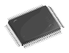
Fine pitch packages are also available with leads on all four sides of the package known as quad flat packs (QFPs). The QFP uses a gull-wing lead form, which complicates the automatic handling of the packages since they can not be supplied in plastic tubes like the dual-in-line (DIP) package. Because of this, each package is housed in its own protective compartment and shipped in trays known as “waffle packs†or matrix trays. The major disadvantage of gull wing packages is that they are susceptible to lead damage and distortion of lead planarity during shipping, handling, and placement. Loss of lead planarity in a fine pitch package may be overcome to certain extent if hot bar soldering is used instead of reflow soldering. Also the lower package thickness compounds the thermal problems and therefore the boards should be suitably designed to allow good thermal conductivity through heat spreaders if necessary. Placement and inspection accuracies required will be more demanding for fine pitch components due to closer lead spacing.
Given below is a QFP package.
QFP - Line Diagram

Actual Sample

QFP Lead

