The Internet is a global, public network with IP subnets connected by routers and exchanging packets. Both Ethernet and IP use globally unique network addresses that can be used as the basis for a truly global network. Ethernet MAC addresses come from the IEEE and IP subnet addresses come from various Internet authorities. (IP also employs a naming convention absent in Ethernet, but we'll ignore that in this discussion.) The key differences in how these addresses are assigned make all the difference when it comes to the basic functions of a bridge as opposed to a router.
All devices on LANs that are attached to the Internet have both MAC layer and IP addresses. Frames and packets contain both source and destination addresses in their headers.
In general:

Virtual Local Area Network (VLAN) creates a separate broadcast domain in layer 2 network. VLANs can also help create multiple layer 3 networks on a single physical infrastructure.
Address Resolution: ARP is the Address Resolution Protocol, which maintains a table named as ARP table. Sending IP packets on a multi access network requires mapping from an IP address to a media access control (MAC) address (the physical or hardware address).
In an Ethernet environment, ARP is used to map a MAC address to an IP address. ARP dynamically binds the IP address (the logical address) to the correct MAC address. Before IP unicast packets can be sent, ARP discovers the MAC address used by the Ethernet interface where the IP address is configured.
Hosts that use ARP maintain a cache of discovered Internet-to-Ethernet address mappings to minimize the number of ARP broadcast messages. To keep the cache from growing too large, an entry is removed if it is not used within a certain period of time. Before sending a packet, the host searches its cache for Internet-to-Ethernet address mapping. If the mapping is not found, the host sends an ARP request.
IP addresses are assigned by a central numbering authority called the Internet Assigned Numbers Authority (IANA). IANA ensures that addresses are globally unique where needed and has a large address space reserved for use by devices not visible outside their own networks.
IPv4 addressing: IPv4 addresses are 32-bit numbers that are typically displayed in dotted decimal notation. A 32-bit address contains two primary parts: the network prefix and the host number.
All hosts within a single network share the same network address. Each host also has an address that uniquely identifies it. Depending on the scope of the network and the type of device, the address is either globally or locally unique. Devices that are visible to users outside the network (webservers, for example) must have a globally unique IP address. Devices that are visible only within the network must have locally unique IP addresses.
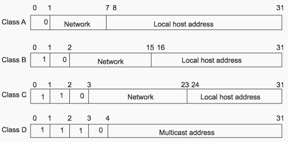
IPv4 classful addressing: To provide flexibility in the number of addresses distributed to networks of different sizes, 4-octet (32-bit) IP addresses were originally divided into three different categories or classes: class A, class B, and class C. Each address class specifies a different number of bits for its network prefix and host number:
In binary format, with an x representing each bit in the host number, the three address classes can be represented as follows:
00000000 xxxxxxxx xxxxxxxx xxxxxxxx (Class A)
00000000 00000000 xxxxxxxx xxxxxxxx (Class B)
00000000 00000000 00000000 xxxxxxxx (Class C)
Subnetting: Subnetting an IP Network is done primarily for better utilization of available IP address space, and routing purpose. Other reasons include better organization, use of different physical media (such as Ethernet, WAN, etc.), and securing network resources.
A subnet mask enables you to identify the network and node parts of the address. The network bits are represented by the 1s in the mask, and the node bits are represented by the 0s. A logical AND operation between the IP address and the subnet mask provides the Network Address.
For example, using our test IP address and the default Class C subnet mask, we get:
192.189.210.078: 1100 0000.1011 1101.1101 0010.0100 1110 Class C IP Address
255.255.255.000: 1111 1111.1111 1111.1111 1111.0000 0000 Default Class C subnet mask
192.189.210.0 1100 0000 1011 1101 1101 0010 0000 0000
As can be seen above, by using and AND operator, we can compute the network portion of an IP address. The network portion for the IP address given in the above example is 192.189.210.0, and the host portion of the IP address is 078.
Below fig. Shows the format of IP address classes

Subnetwork Mask Format: IPv4 subnetwork masks specified in one of the two ways: dotted decimal or prefix length notation.
Dotted decimal notation expresses IP addresses and masks in dotted quads - four octets separated by dots (A.B.C.D). In this format, each octet in the address or mask is represented as a decimal number and the dots are used as octet separators.
For example, an IP address and subnetwork mask in dotted decimal notation would appear as 192.168.100.1 255.255.255.0
Prefix length notation (often called network prefix format) allows for more efficient allocation of IP addresses than the old Class A, B, and C address scheme. The prefix length is the number of leftmost contiguous bits equal to 1 in the subnetwork mask. This format appears immediately following the dotted decimal IP address using a /N format.
For example, the same IP address and subnetwork mask mentioned above would appear as follows using /N format: 192.168.100.1/24
A network mask is used to separate the network information from the host information about an IP address. Figure below shows the network mask 255.0.0.0 applied to network 10.0.0.0. The mask in binary notation is a series of 1s followed by a series of contiguous 0s. The 1s represent the network number; the 0s represent the host number. The sample address splits the IP address 10.0.0.1 into a network portion of 10 and a host portion of 0.0.1.

Classes A, B, and C have the following natural masks, which define the network and host portions of each class:
Class A natural mask 255.0.0.
Class B natural mask 255.255.0.0
Class C natural mask 255.255.255.0
The use of masks can divide networks into subnetworks by extending the network portion of the address into the host portion. Subnetting increases the number of subnetworks and reduces the number of hosts.
For example, a network of the form 10.0.0.0 accommodates one physical segment with about 16 million hosts on it. Below figure shows how the mask 255.255.0.0. is applied to network 10.0.0.0. The mask divides the IP address 10.0.0.1 into a network portion of 10, a subnet portion of 0, and a host portion of 0.1. The mask has borrowed a portion of the host space and has applied it to the network space. The network space of the class 10 has increased from a single network 10.0.0.0 to 256 subnetworks, ranging from 10.0.0.0 to 10.255.0.0. This process decreases the number of hosts per subnet from 16,777,216 to 65,536.

Classless Addressing with CIDR
CIDR is a system of addressing that improves the scaling factor of routing in the Internet. CIDR does not use an implicit mask based on the class of network. In CIDR, an IP network is represented by a prefix, which is an IP address and an indication of the leftmost contiguous significant bits within this address.
For example, without CIDR, the class C network address 192.56.0.0 would be an illegal address. With CIDR, the address becomes valid with the notation: 192.56.0.0/16. The /16 indicates that 16 bits of mask are being used (counting from the far left). This would be similar to an address 198.32.0.0. with a mask of 255.255.0.0.
A network is called a supernet when the prefix boundary contains fewer bits than the network's natural mask. For example, a class C network 192.56.10.0 has a natural mask of 255.255.255.0. The representation 192.56.0.0/16 has a shorter mask than the natural mask (16 is less than 24), so it is a supernet. Network Mask is a 32bit value that identifies the network to which an IP address belongs.
The CIDR Value table is as shown below:
| Subnet Mask | CIDR value |
|---|---|
| 255.255.0.0 | /16 |
| 255.255.128.0 | /17 |
| 255.255.192.0 | /18 |
| 255.255.224.0 | /19 |
| 255.255.240.0 | /20 |
| 255.255.248.0 | /21 |
| 255.255.252.0 | /22 |
| 255.255.254.0 | /23 |
Important points to note:
1. A subnet mask is used to determine the break between network and host subsections of an IP addressing
2. VLSM allows for conservation of address space by allowing the subnet mask to allocate bits across the entire range of the IP address
3. An address where all the host bits are set to 1 is the broadcast
4. An address where all the host bits are set to 0 is the network
5. There are 2n-2 addresses in a CIDR block, where n is the number of host bits
IPv6 addressing: IP version 6 (IPv6) increases the size of the IP address from the 32 bits found in IPv4 to 128 bits. This increased size provides for a broader range of addressing hierarchies and a much larger number of addressable nodes.
IPv6 addresses consist of eight hexadecimal groups. Each hexadecimal group, separated by a colon (:), consists of a 16-bit hexadecimal value.
The following is an example of the IPv6 format: xxxx:xxxx:xxxx:xxxx:xxxx:xxxx:xxxx:xxxx
A group of xxxx represents the 16-bit hexadecimal value. Each individual x represents a 4-bit hexadecimal value.
The following is an example of a possible IPv6 address: 4FDE:0000:0000:0002:0022:F376:FF3B:AB3F
Comparison between IPv4 and IPv6 addressing
| IPv4 | IPv6 |
|---|---|
| 32-bit (4 byte) address supporting 4,294,967,296 address (although many were lost to special purposes, like 10.0.0.0 and 127.0.0.0) | 128-bit (16 byte) address supporting 228 (about 3.4 x 1038) addresses |
| NAT can be used to extend address limitations | No NAT support (by design) |
| IP addresses assigned to hosts by DHCP or static configuration | IP addresses self-assigned to hosts with stateless address auto-configuration or DHCPv6 |
IPv4 and IPv6 addressing concepts:
| IPv4 | IPv6 |
|---|---|
| Mulitcast address space at 224.0.0.0/4 | Multicast address space at FF00::/8 |
| Has broadcast addresses for all devices | No such concept in IPv6 (uses multicast groups) |
| Uses 0.0.0.0 as unspecified address | Uses :: as unspecified address |
| Uses 127.0.0.1 as loopback address | Uses ::1 as loopback address |
| Supports globally unique "public" addresses | Supports globally unique unicast addresses |
| Uses 10.0.0.0/8, 172.16.0.0/16, and 192.168.0.0/16 as "private" addresses | Uses FD00::/8 as unique local addresses |
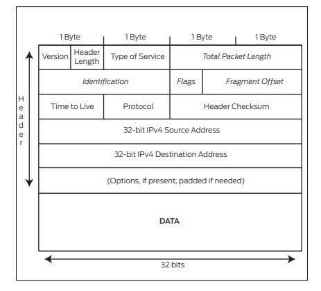
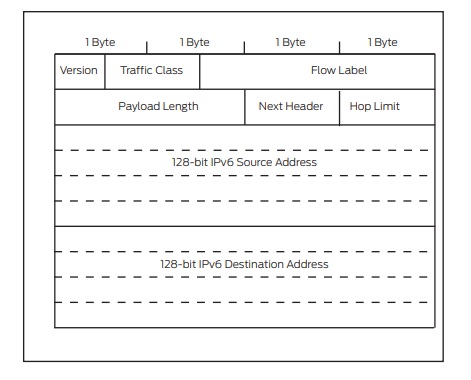
Figure below compare the header of a IPv4 packet and an IPv6 packet

Fig: IPv4 Header

Fig: IPv6 header
IPv6 packets have their own frame Ethertype value, 0x86dd, making it easy for receivers that must handle both IPv4 and IPv6 to distinguish the frame content on the same interface. The IPv6 header is comprised of the following fields:
IPv6 Host Addressing: IPv4 hosts are fairly easy to configure: usually, the network interface has one IPv4 address. When coupled with the default router - if there is a way off the subnet- the host has everything it needs to decide where things go. But IPv6 does much more. In contrast to IPv4 hosts, IPv6 hosts (end devices) normally have multiple addresses on each interface. But these multiple addresses greatly simplify the operation of the IPv6 network layer (finding network neighbors, routers, and so on).
Unicast addresses
Multicast addresses
All IPv6 router interfaces also listen for traffic on the following multicast addresses:
What is Reverse Path Forwarding and why it is required: To protect against IP spoofing, and some types of denial-of-service (DoS) and distributed denial-of-service (DDoS) attacks, Unicast Reverse-path Forwarding (RPF) verifies that packets are arriving from a legitimate path. It does this by checking the source address of each packet that arrives on an untrusted ingress interface and, comparing it to the forwarding-table entry for its source address.
Unicast RPF is supported for the IPv4 and IPv6 protocol families. There are two modes of unicast RPF, strict mode, and loose mode.
The default is strict mode, which means the switch forwards a packet only if the receiving interface is the best return path to the packet's unicast source address. Strict mode is useful in identifying untrusted interfaces and sending packets via the best route.
The other mode is loose mode, which means the system checks to see if the packet has a source address with a corresponding prefix in the routing table, but it does not check whether the receiving interface is the best return path to the packet's unicast source address.